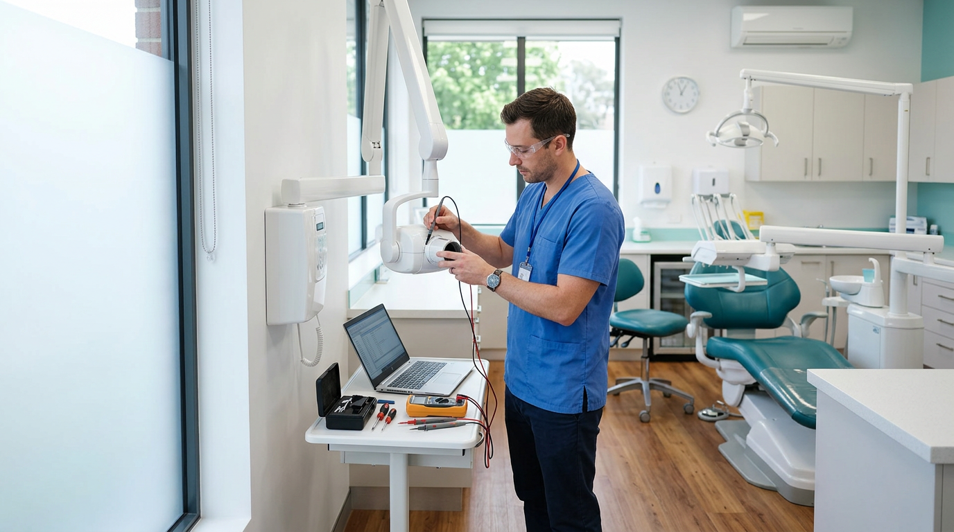
What does the Err 1 error mean on a Gendex Expert DC?
The Gendex Expert DC is a wall-mounted intraoral X-ray unit with a direct-current (DC) generator, operating at about 65 kV and 7 mA. When it works normally, the display shows the exposure time in seconds, for example 0.320 s. If “Err 1” appears instead, the unit blocks the exposure. This is a protective function, not a random display fault.
According to the manufacturer’s service documentation, Err 1 relates to the power supply: the mains voltage is outside the range the unit accepts (108–132 V for the 120 V setting or 198–253 V for the 220 V setting), or the voltage-selection jumper does not match the actual voltage at the practice. Only when supply and configuration are correct do we look for faults in the unit’s electronics.
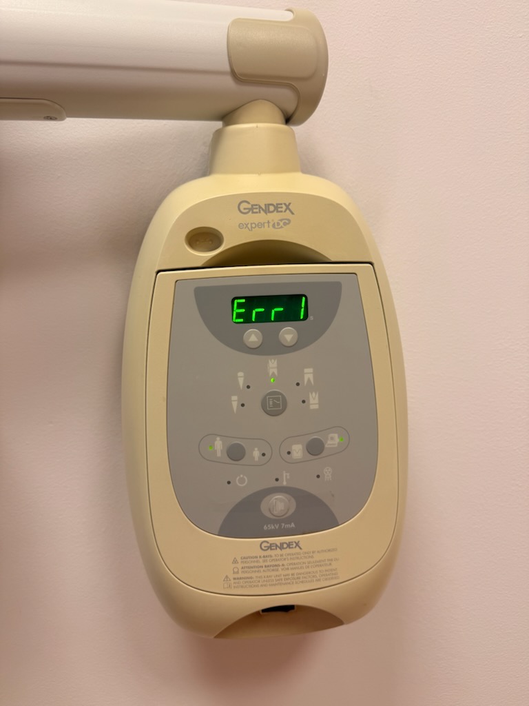
Gendex Expert DC at a glance and normal panel operation
The unit is mounted on a wall arm and controlled from the panel on the head. LEDs show the selected tooth programme, patient type (adult / child) and image receptor type, while the arrow buttons change the exposure time. The photo below shows the panel of a working unit with 0.320 s set.
| Parameter | Value | Notes |
|---|---|---|
| Tube voltage | 65 kV (60–70 kV range) | Value printed on the panel |
| Tube current | 7 mA | Direct-current (DC) generator |
| Exposure time | shown in seconds | e.g. 0.320 s in the photo |
| Supply | about 220–230 V or 120 V | Depends on the voltage-select jumper position |
| Mounting | wall arm | Head with panel and control electronics |
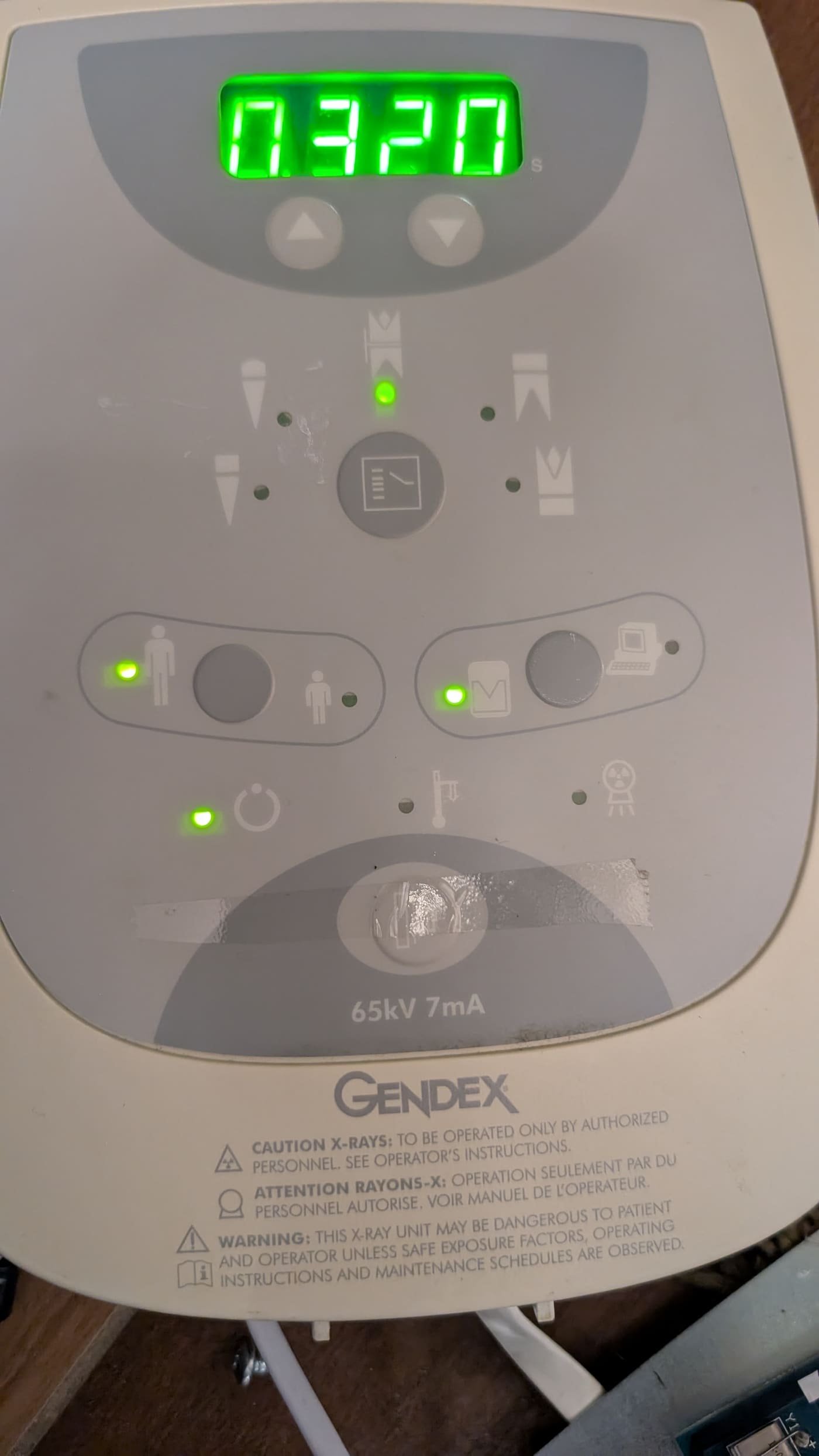
The most common causes of Err 1
The same message can have several sources. The table orders them from the simplest to those requiring electronics repair. The first two come directly from the manufacturer’s documentation; the rest are typical checkpoints in service diagnosis.
| Cause | Symptom | Checked by |
|---|---|---|
| Mains voltage out of range | Err 1 at power-on or on exposure, other equipment affected | Electrician |
| Voltage jumper set incorrectly | Err 1 from first start, after relocation or after part replacement | Service engineer |
| Loose connectors or wires in the head | Intermittent error depending on arm movement | Service engineer |
| Mains filter or input fuses | Unstable electronics supply, random messages | Service engineer |
| Converter / Inverter board | Err 1 despite correct voltage at the socket | Service engineer |
| Logic / Control board | Wrong supply-voltage readings, unstable panel | Service engineer |
What the practice can check before calling service
These steps are safe and do not require opening the unit head:
- Switch the unit off, wait one minute and switch it on again; note whether Err 1 appears immediately or only after arm movement or an exposure attempt.
- Check whether high-load devices (compressor, autoclave, air conditioning) share the circuit and whether the error appears when they start.
- Photograph the display and note the model, serial number and date of the last inspection.
- Note whether the unit was recently moved, reconnected or whether electrical work was done in the building.
- Ask an electrician to check the supply circuit (see next section).
Do not open the head housing. It contains high-voltage capacitors that stay charged after disconnecting the power, and parts of the X-ray generator.
Measuring supply voltage: why an electrician should do it
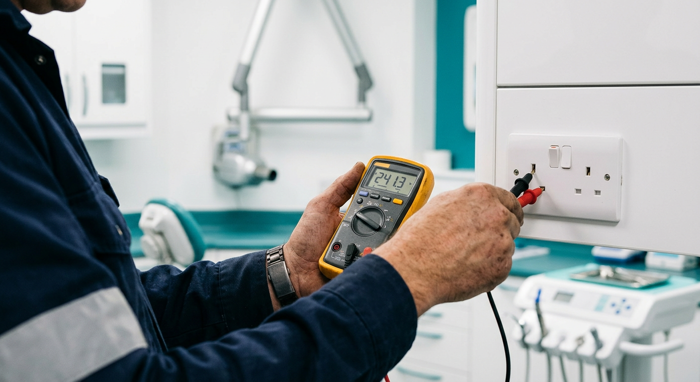
Because Err 1 concerns voltage, the first step is to measure the real voltage at the socket feeding the unit, under load rather than idle. The electrician checks line voltage, protective-earth continuity, loop impedance and the voltage drop when other loads switch on.
A common problem in dental practices is a thin or long supply line shared with a compressor or sterilizer. A 230 V grid fits the 198–253 V window, yet a brief drop during exposure is enough to trigger the error.
Service diagnosis step by step: Converter and Logic boards
When the installation is fine, the engineer moves on to the unit. We follow a fixed order so that parts are never replaced blindly:
- Verify the voltage-select jumper and jumper JP1 on the Converter board (for the 120 V version JP1 is cut to enable the neutral fuse).
- Inspect the mains filter (a Schaffner FN2030-10-06, 10 A, is visible in the photo) and input fuses.
- Visually inspect the Converter / Inverter board: electrolytic capacitors, transformers, diodes, power connectors, signal ribbons, signs of overheating.
- Check the Logic / Control board (124-0293): logic supply, status LEDs, DIP switch settings, connectors and solder joints.
- Measure voltages at the board test points and verify that the mains-detection circuit reports correct values.
- Run a test exposure with parameter measurement after the fault is fixed.
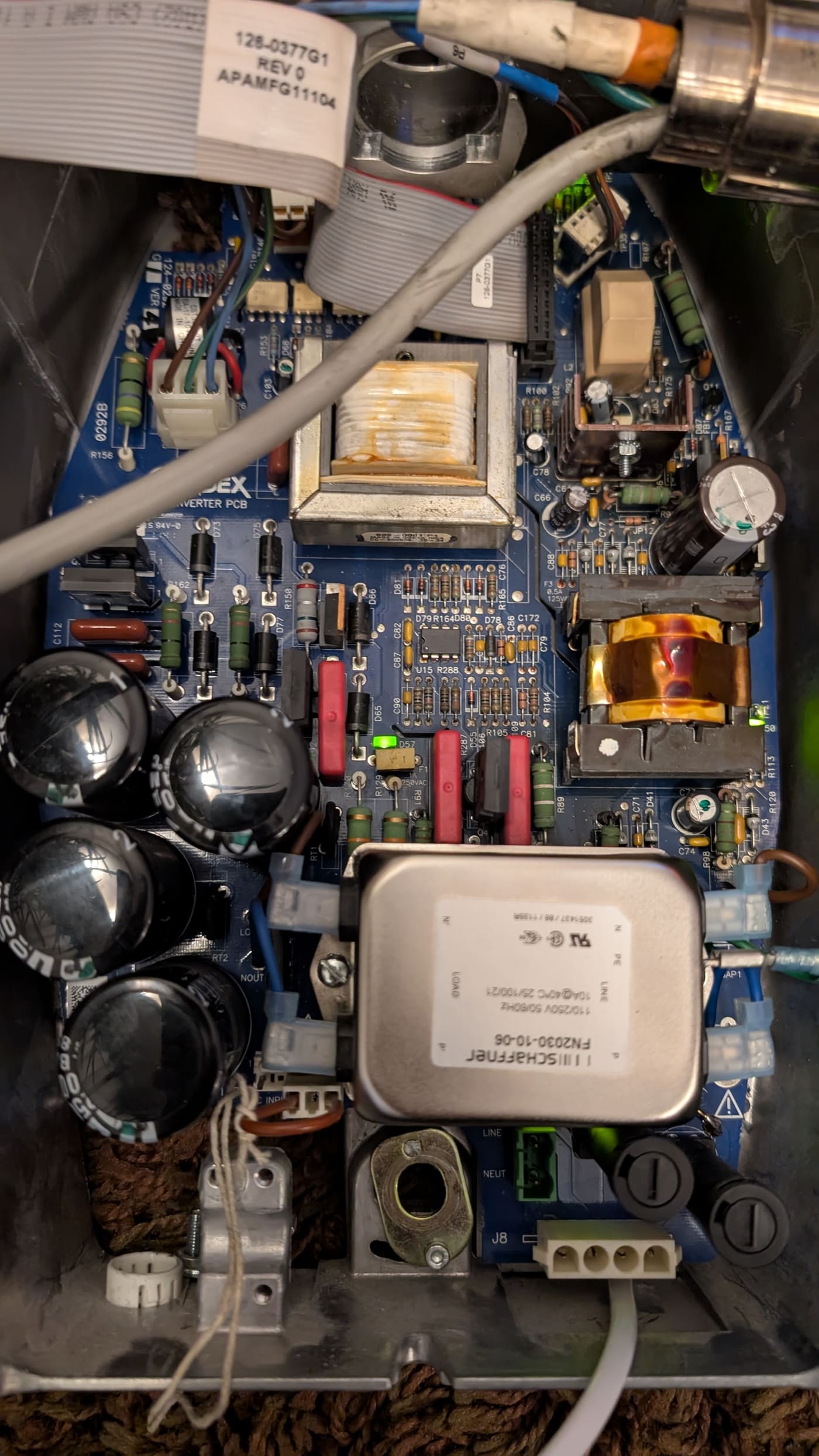
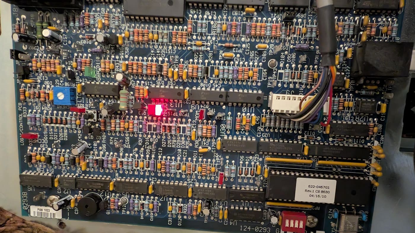
Repair: from setting a jumper to replacing a board
The scope depends on the cause found. Often a configuration or supply correction is enough, but sometimes the electronics need repair. Importantly, boards can frequently be repaired at component level without buying a whole module.
| Action | When used | Result |
|---|---|---|
| Correct voltage-select jumper | Configuration does not match the mains | Unit works again after testing |
| Improve the practice supply | Voltage drops or weak circuit | Stable operation, no repeat error |
| Replace filter, fuses, connectors | Damaged input components | Electronics supply restored |
| Repair Converter / Logic board | Damaged electronic components | Repair without replacing the module |
| Replace board | Repair uneconomical or impossible | Working unit after calibration and test |
Quotes are always individual and depend on the diagnosis. After the repair we issue a service report with measurement results.
Safety and radiation protection after repair
An X-ray unit emits ionising radiation, so after any work on the generator or electronics we verify correct operation, including repeatability and accuracy of exposure time, tube voltage and current, and safe function of the exposure button.
Radiation-protection and acceptance-testing requirements derive from Directive 2013/59/Euratom across the European Union and national laws such as the Polish Atomic Law. For units outside Poland we adapt the documentation to local rules.
Dental X-ray service across Poland and Europe
Our base is Knurów in Silesia, from where we reach practices within about 50 km of Gliwice and Rybnik. For customers elsewhere in Poland and in other European countries we offer remote consultation based on photos and the error description, and repair of electronic boards sent by mail. On-site visits outside Silesia are arranged individually.
| Area | Service method | Contact hours |
|---|---|---|
| Silesia (Gliwice, Rybnik, Knurów area) | Engineer visit to the practice | Working days, 8:00–16:00 |
| All of Poland | Remote consultation, board repair by mail, visit by arrangement | Working days, 8:00–16:00 |
| Europe | Remote consultation and board repair by mail | Working days, 8:00–16:00 (CET) |
Other X-ray units we service
Besides the Gendex Expert DC we work on these intraoral units and imaging systems:
- Gendex (including GX-S and GX-770 models),
- Sirona / Dentsply Sirona – Heliodent,
- Planmeca – ProX, Intra,
- Carestream Dental – CS 2100 and CS 2200,
- Vatech – EzRay Air and EzSensor sensors,
- Owandy / Trophy and Genoray,
- digital RVG sensors and phosphor plate scanners.
How to report an X-ray unit fault
Call or write on working days between 8:00 and 16:00 (CET). Prepare the unit model, serial number, a photo of the display with the error and when it first appeared. The more precise the description, the faster we find the cause and plan the repair.
Frequently asked questions
- What does Err 1 mean on a Gendex Expert DC?
- Err 1 concerns the power supply: mains voltage is outside the accepted range (108–132 V or 198–253 V) or the voltage-select jumper does not match the installation. If supply is correct, a Converter or Logic board fault may be the cause.
- Can I open the head and check the jumper myself?
- We do not recommend it. The head contains high-voltage capacitors that remain charged after disconnecting the power and parts of the X-ray generator. Supply configuration should be checked by a service engineer.
- Does Err 1 mean the unit is completely broken?
- No. Often the cause is supply or configuration rather than generator damage. Diagnosis shows whether a board repair is needed.
- Do you repair Converter and Logic boards for the Gendex Expert DC?
- Yes, at component level, which often avoids replacing the whole module. Repair is possible on site or by mail.
- Do you serve practices outside Silesia?
- Yes. Across Poland we offer remote consultation, board repair by mail and visits arranged in advance.
- Do you help practices in other European countries?
- Yes, with remote consultation and mailed repair of electronic modules. Documentation is adapted to the user’s country.
- How much does an Err 1 repair cost?
- Quotes are individual and depend on the cause found during diagnosis. Contact us and we will prepare a quote after diagnosing the unit.
- When can I contact you?
- On working days, Monday to Friday, 8:00–16:00 (CET), at +48 504 511 170.
Is your X-ray unit showing an error?
Describe the model and the message and we will help identify the cause and plan the repair.
A-Core MedServis Śląsk, ul. Kołłątaja 2c/LU1, 44-193 Knurów, woj. śląskie
We serve dental practices across Poland and Europe
Dental X-ray service for practices in cities such as: